Overview
I was recently creating a lot of private GKE clusters and wanted to work with them quickly, I was honestly a bit lazy and decided not to create bastions and ssh into as I needed some tools that were installed on my local workstation.
I did a PoC for BGP routing with Cloud VPN which came in handy since that was where most of the work was centered around. The problem I had was my main router is a Unifi DreamMachine Pro which supported IPsec but not BGP, for the stuff I needed BGP was a must so I spent a considerable amount of time trying to get BGP working on a pfSense router behind my main router.
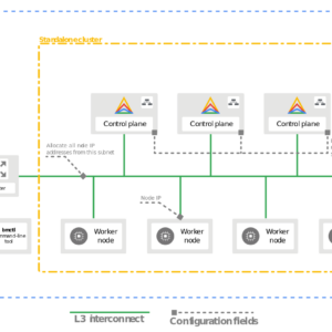
Architecture

Above is my network hardware setup which consists of Unifi gear and 2 Dell servers, running Hyper-V and ESXi. I also have a local DNS server utilizing PiHole routing to 2 upstream Windows Server domain controllers.
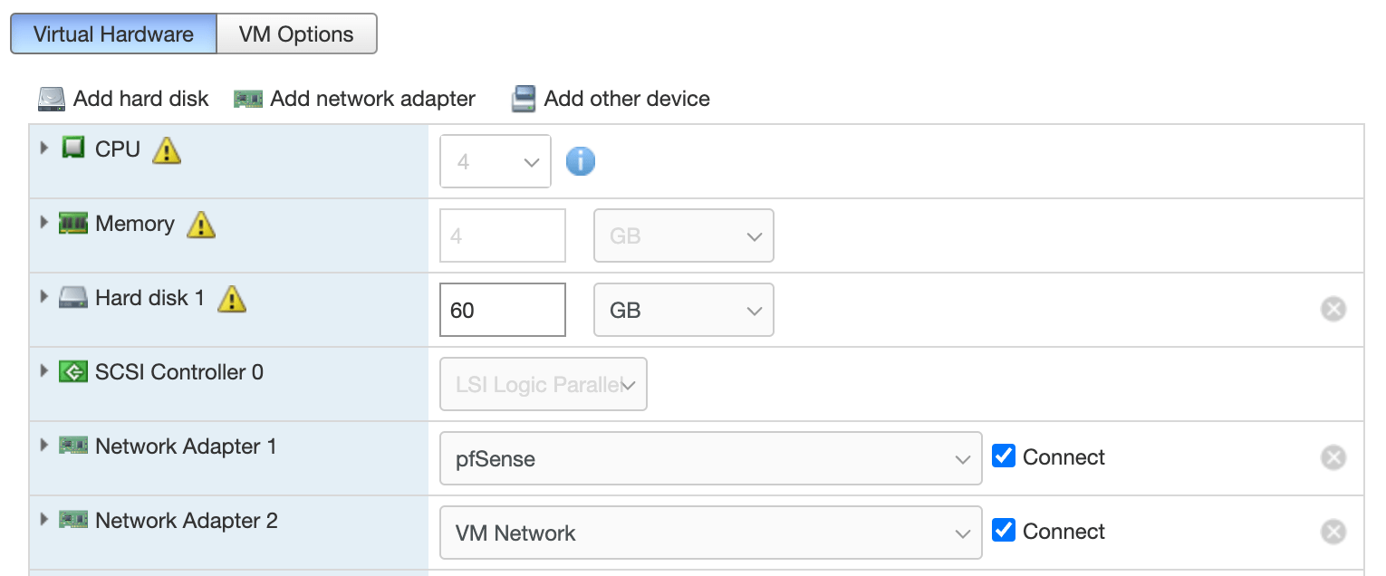
The pfSense router I am using for this setup was virtualized on my ESXi Host and given its own dedicated network for the WAN side.

Above is the detailed architecture and some of my LAN’s so you can see network segregation. The pfSense has two NICs one connecting to its own dedicated network for WAN and one connecting my LAN effectively bridging my to be configured VPN network.
Setup
pfSense Setup
- Download pfSense from https://www.pfsense.org/download/ and extract, I had some issues with the default mac extractor not extracting the .gz file into an iso and had to use gzip instead from cli
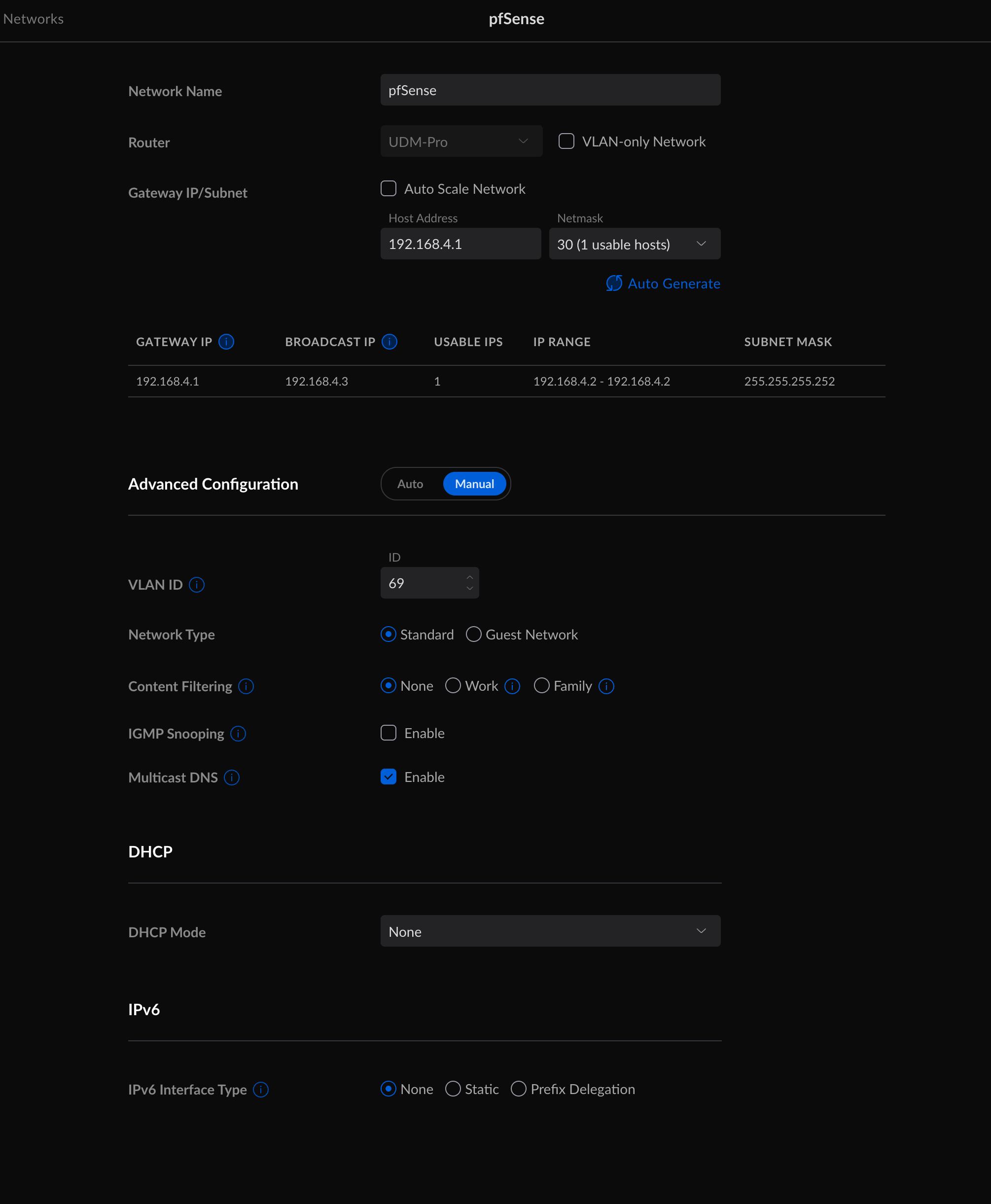
- Create a pfSense dedicated network, I decided to create a /30 network with no DHCP so I could assign it statically through the pfSense interface.
- Create your pfSense VM and add 2 NICs, 1 for the pfSense network and 1 to the network you want yo have access to the VPN.
- Install and configure pfSense, give it a static IP of your WAN in the network range you created as well as one for you LAN
- Navigate to your pfSense LAN IP and finish the configuration there.
- Go to system->package manager and install the package called FRR, we will need this for BGP later.
GCP Setup
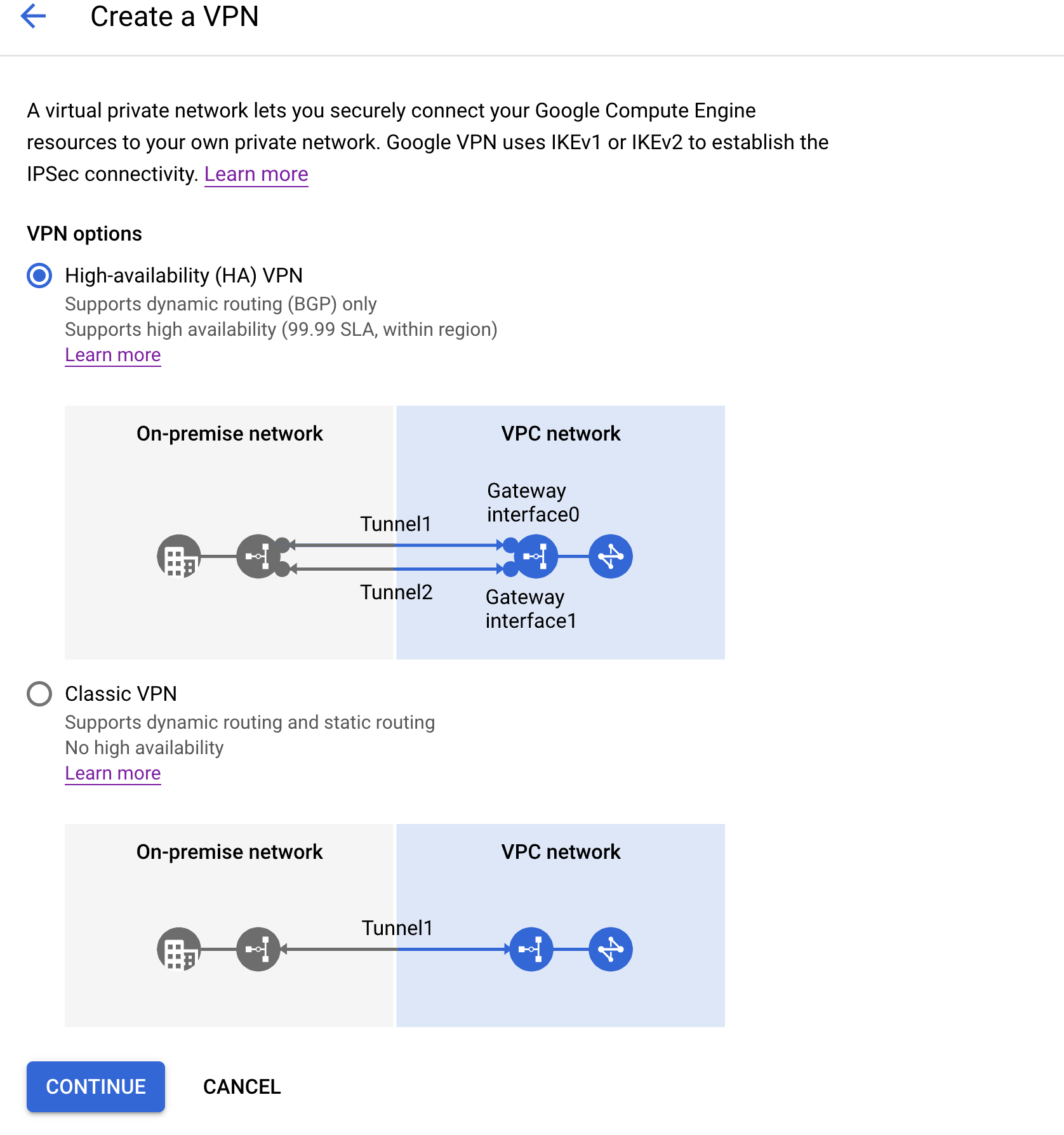
- Create a High-availability VPN in your GCP project
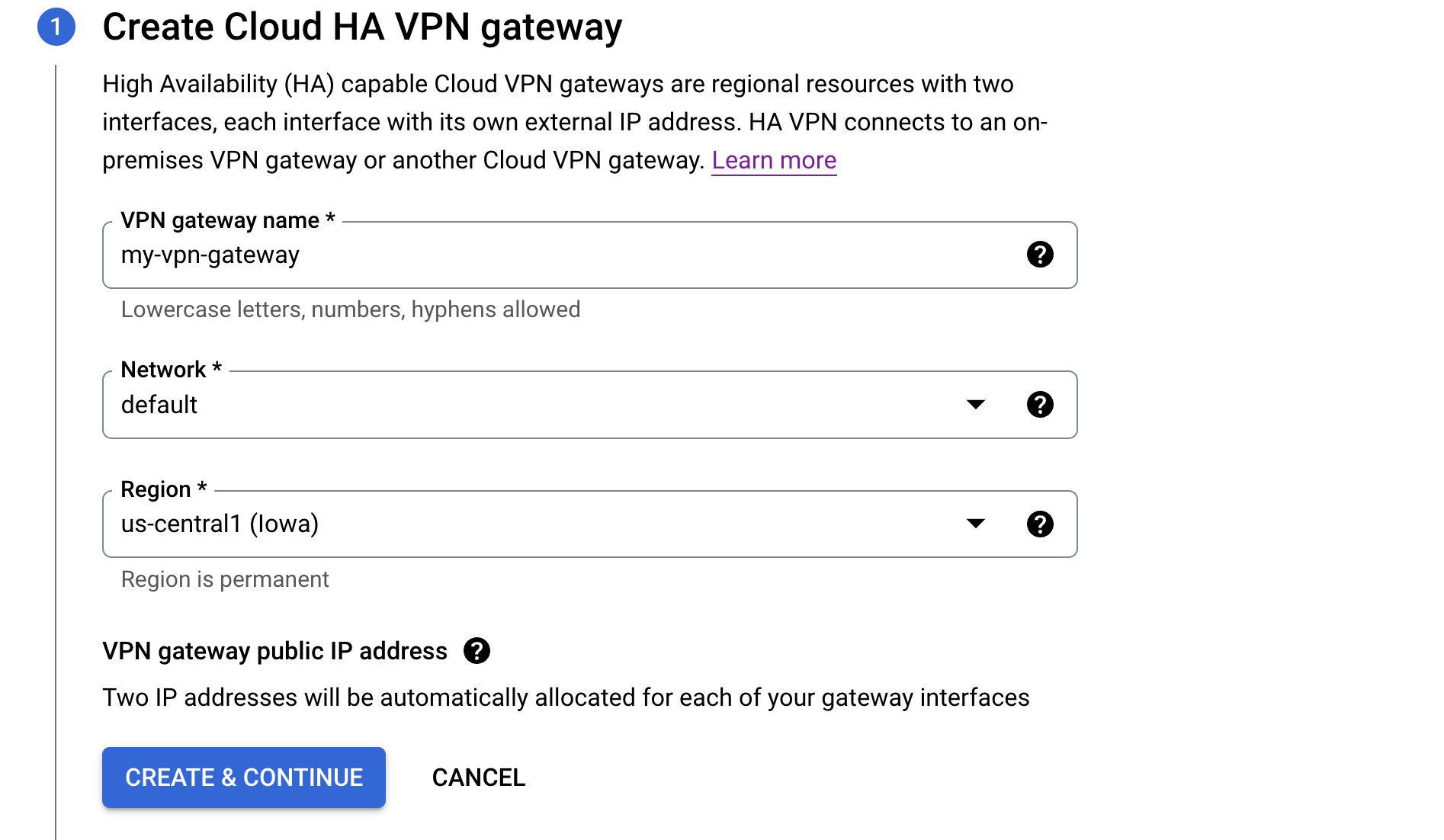
- Name your gateway and select the network you want to VPN to
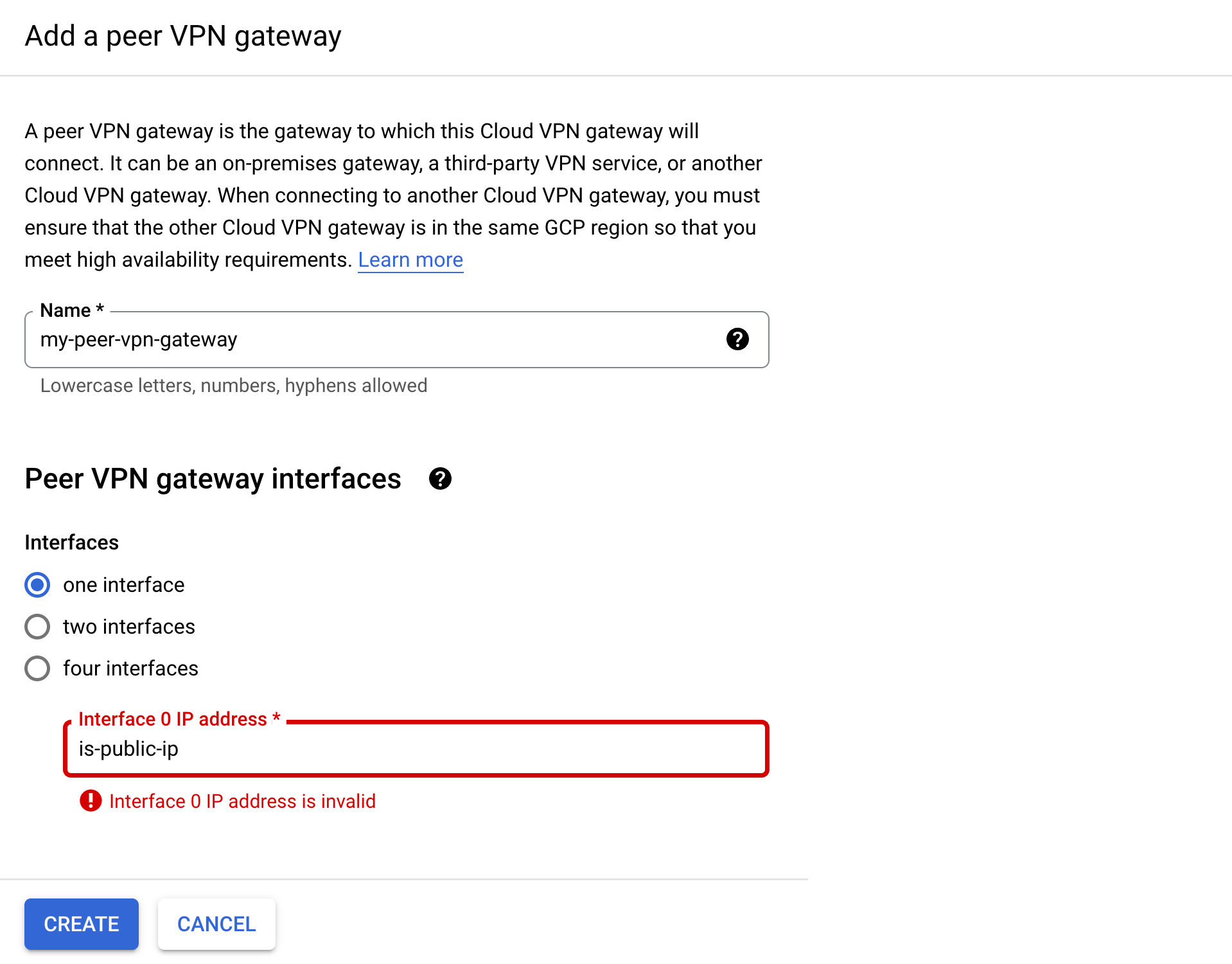
- Create a peer VPN gateway, since I don’t need HA I created one with 1 interface, the interface IP address should be your ISP’s public IP address
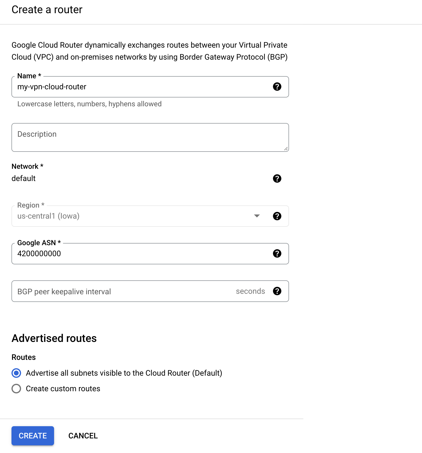
- Next create a cloud router the Google ASN needs to be a ASN you’re not currently using in your project and in ASN range listed when hovering over the ?
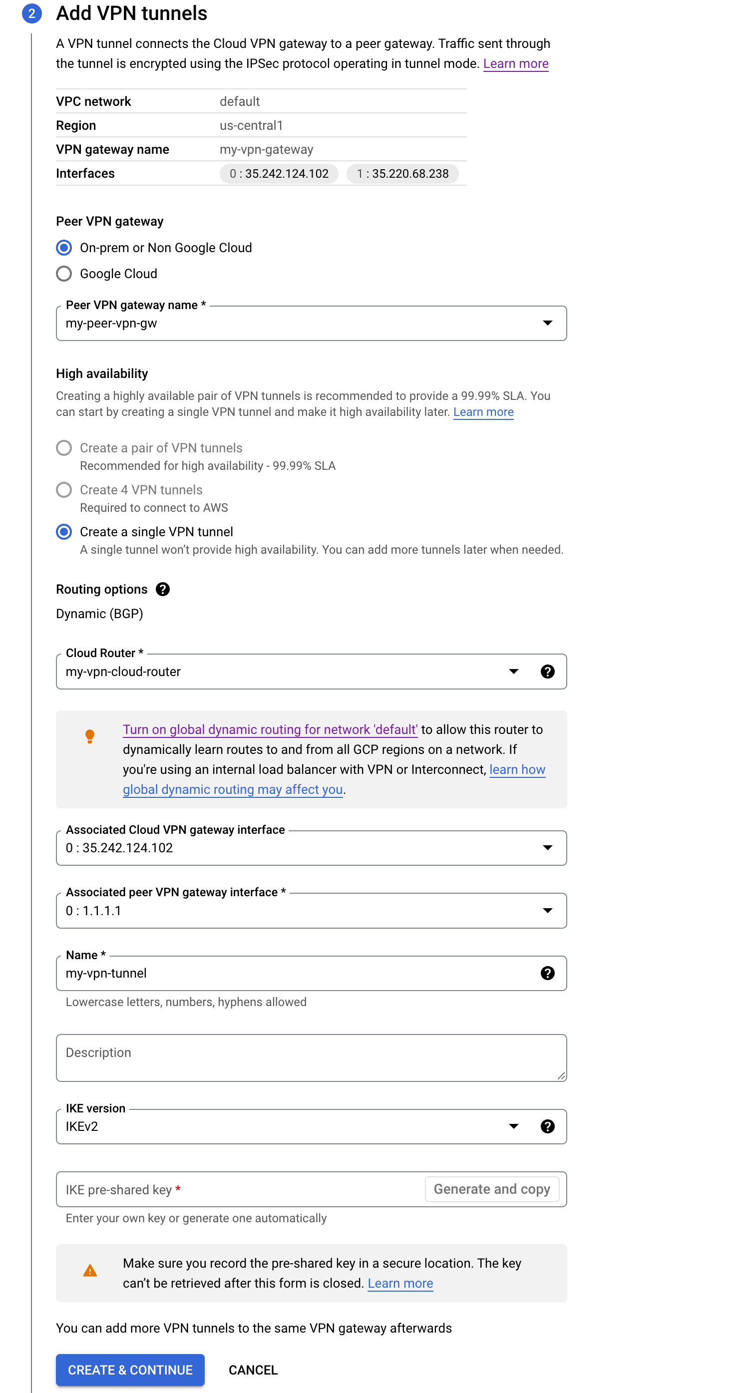
- The configuration page should look like this, now you can generate a IKE key, make sure to document this somewhere you will need it on the pfSense configuration side.
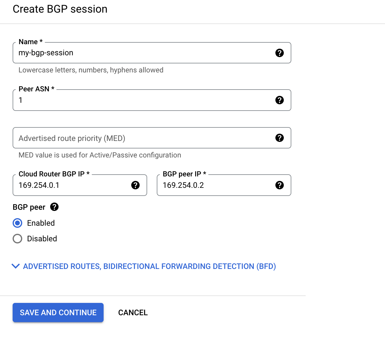
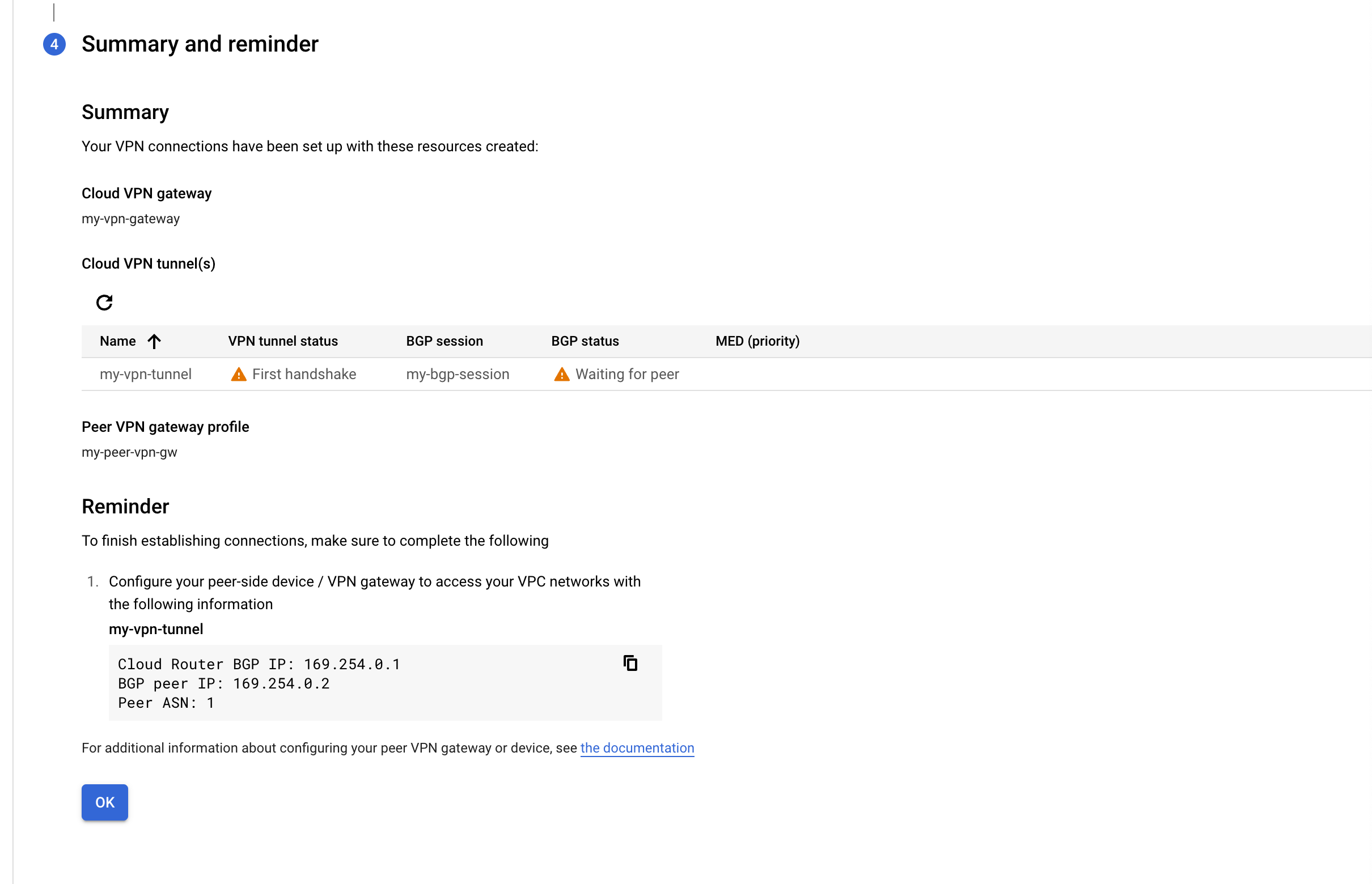
- Next you need to create a BGP session, your Peer ASN can be anything, you will set that up late in pfSense, it just needs to be the same on the GCP and pfSense side. The BGP ip needs to be a /30 link local address. Make sure to write this down as you will need to configure this on the pfSense side.
- Write down your Cloud VPN gateway address, this will be used in the pfSense config side for the VPN.
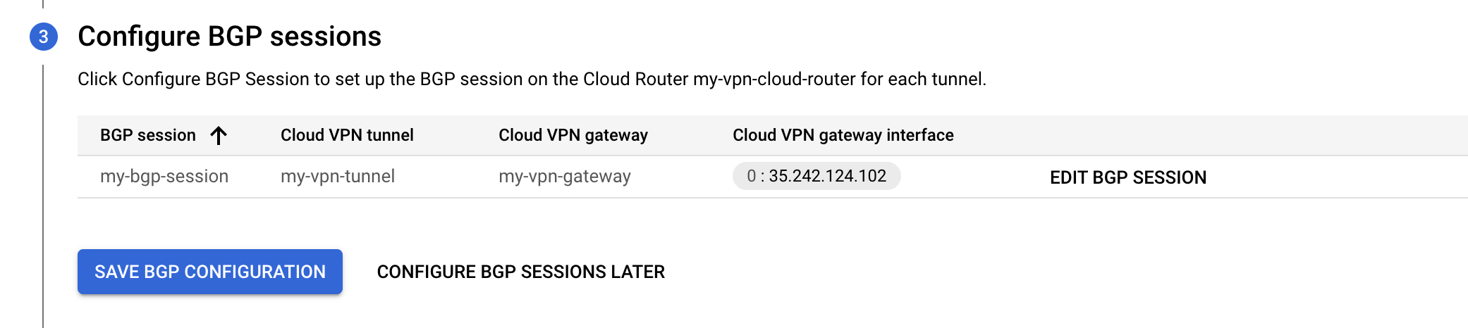
- You should see this page, where you can monitor your VPN and BGP status while configuring your pfSense router.
pfSense Config
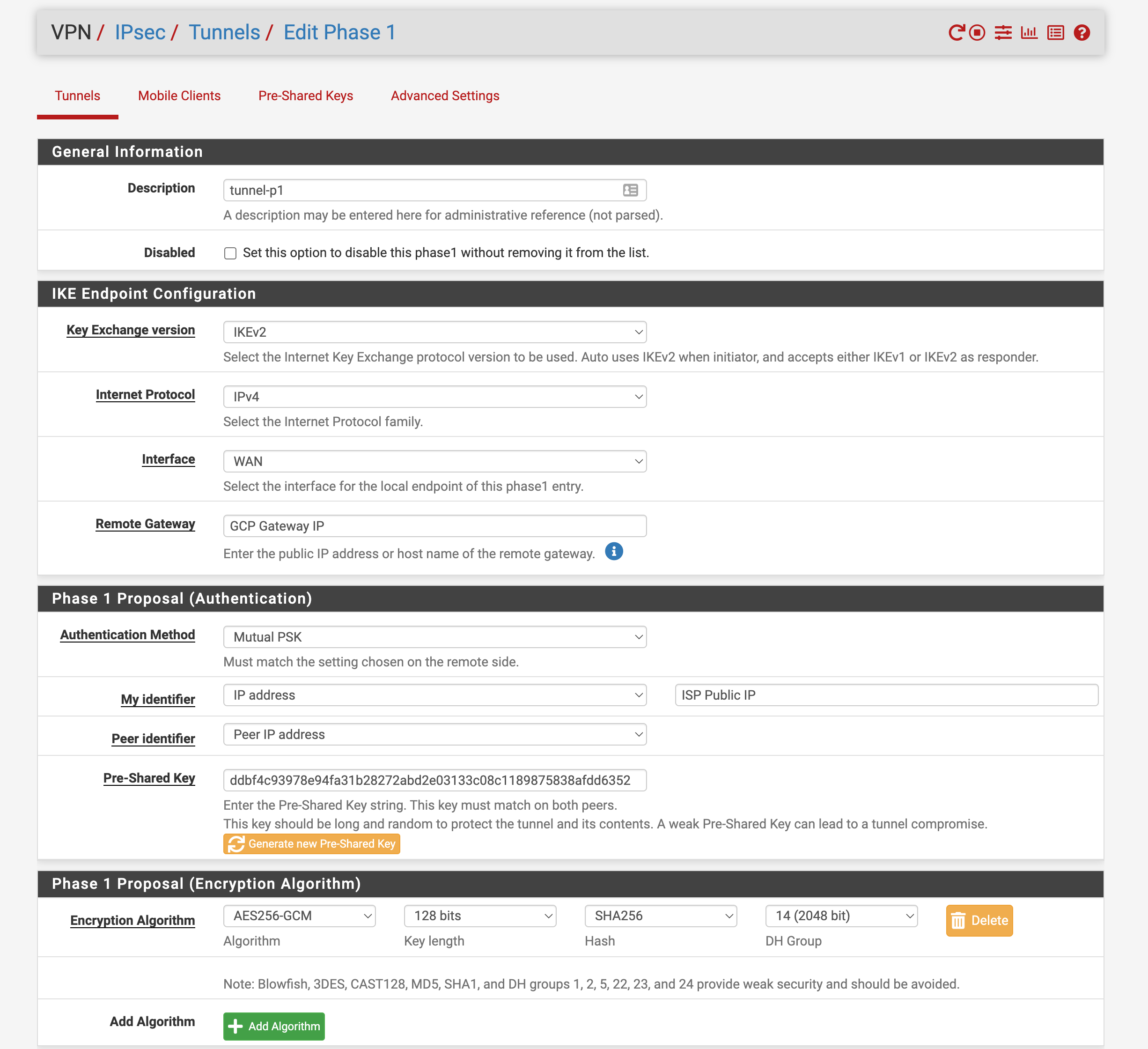
- Navigate to VPN->IPsec and create a new P1 tunnel, replace the IPs with the GCP Gateway IP and your ISP’s public IP, this step is important because since you are behind another router, if you defaulted the My Identifier IP it would advertise your private IP. Paste in the pre-shared key generated from the GCP side and set up encryption as shown below.
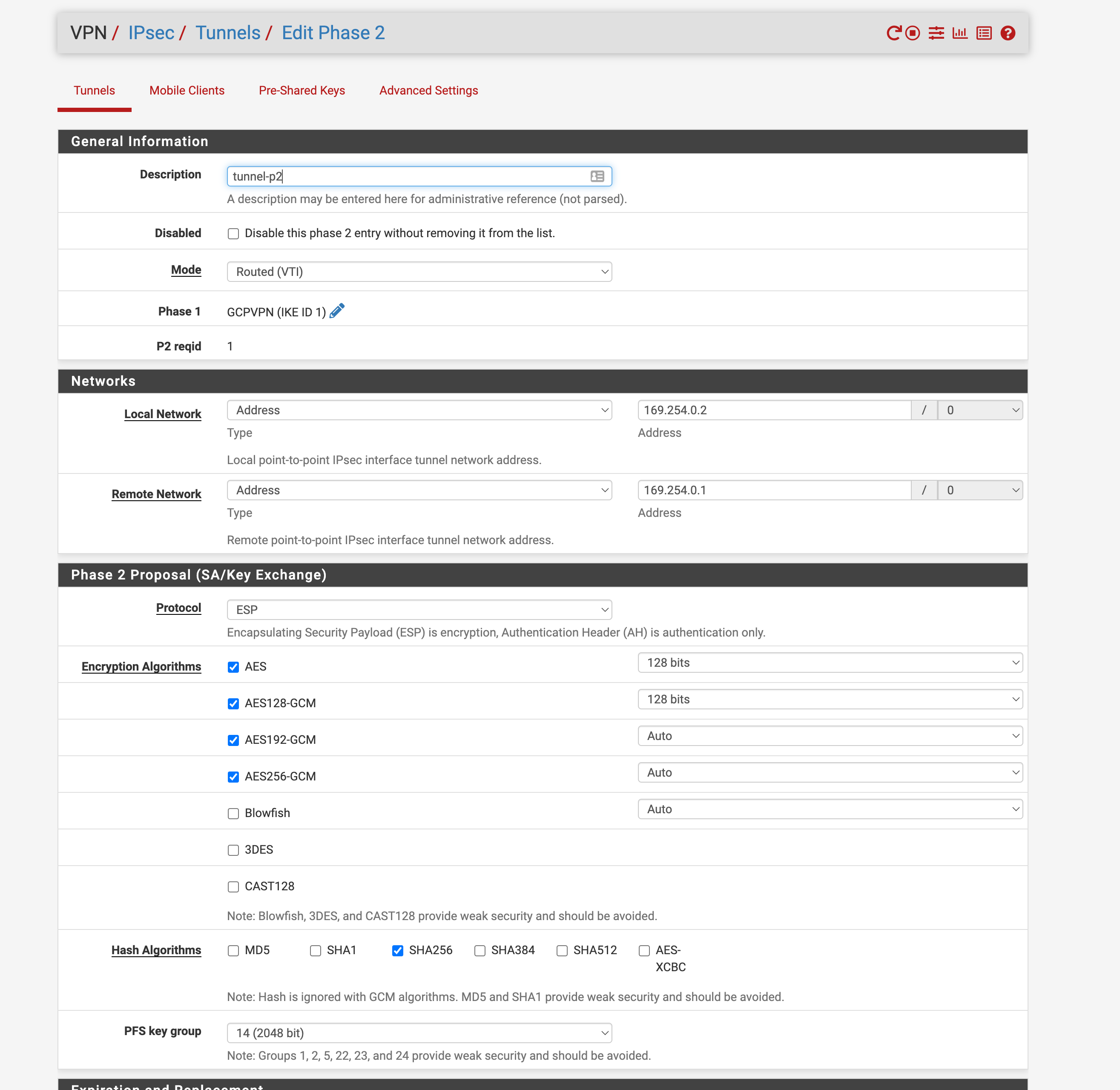
- Configure a P2 tunnel linked to the P1 you just created with the settings below. Filling your local network and remote network address you put in the GCP side. This will allow your BGP routers to communicate via link local addresses when the VPN session is established.
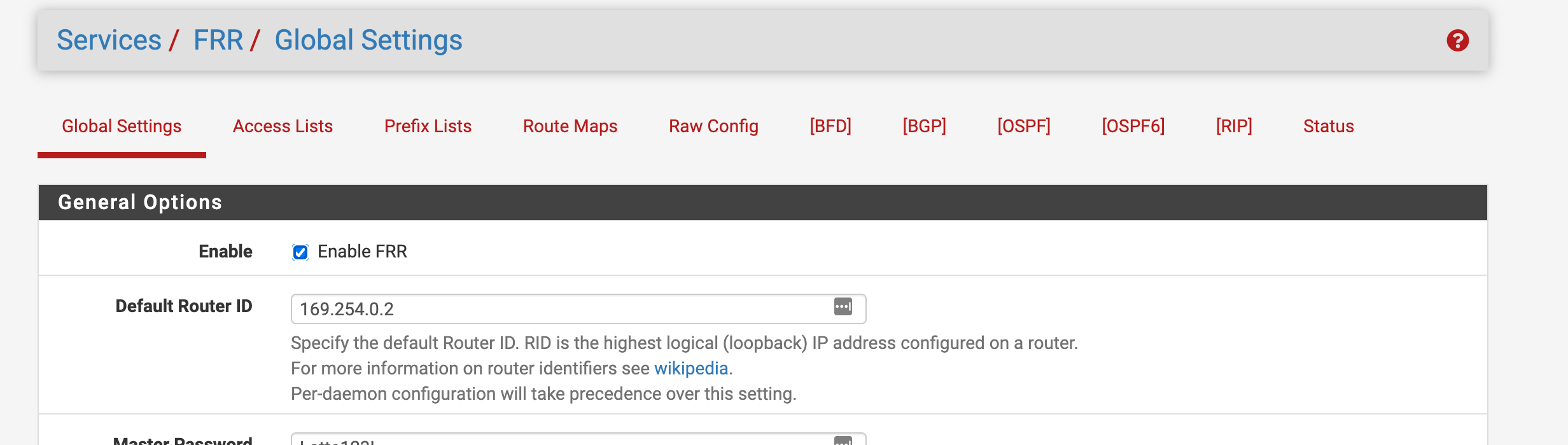
- Navigate to services->FRR->global settings and enable FRR, setting your default router ID as the same one you configured in GCP
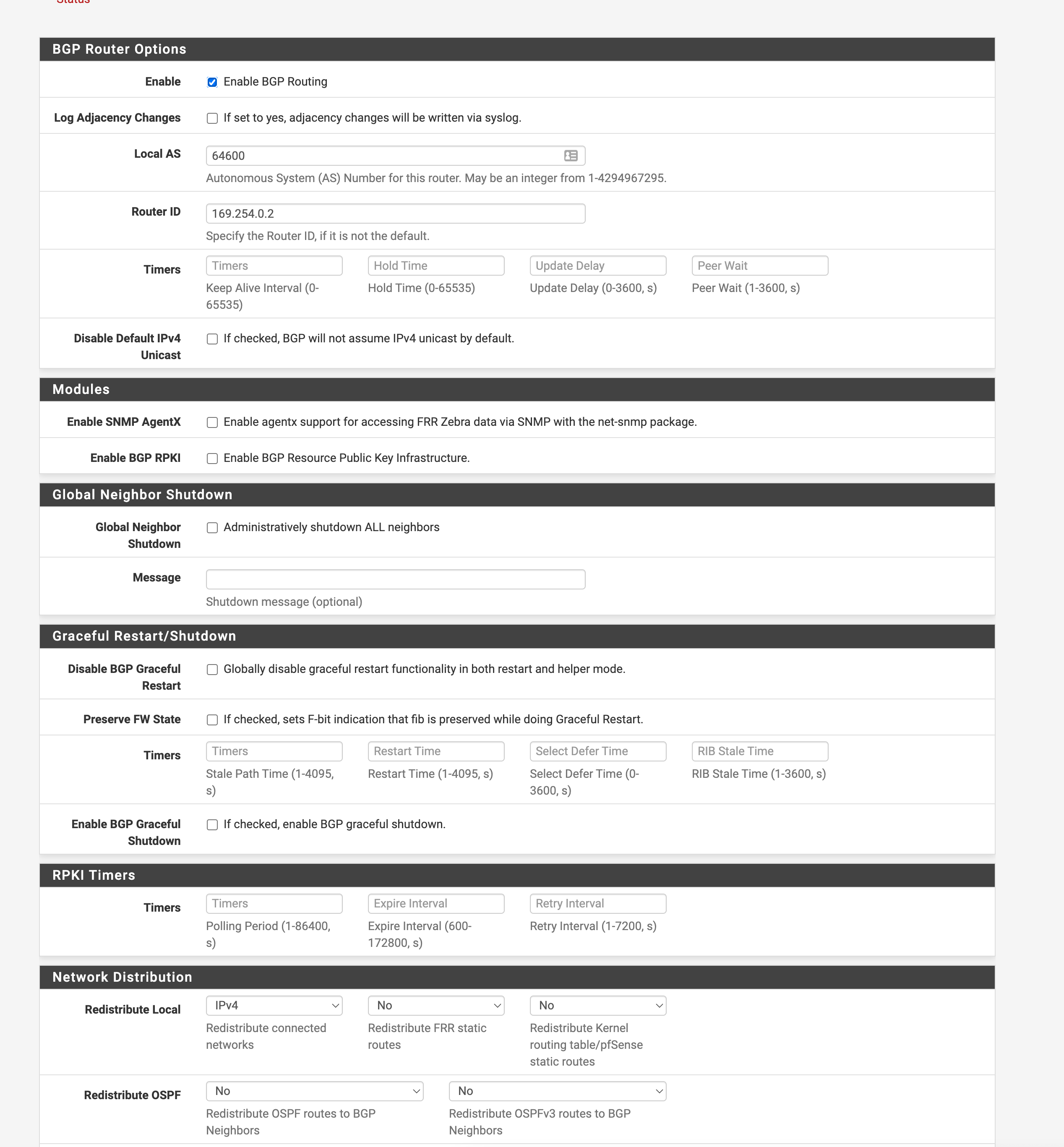
- Navigate to the BGP section of FRR and enable BGP, setting your local AS and router ID to what you configured in GCP. Configure the network distribution section to redistribute local IPv4, this will allow automatic route exports for your local network.
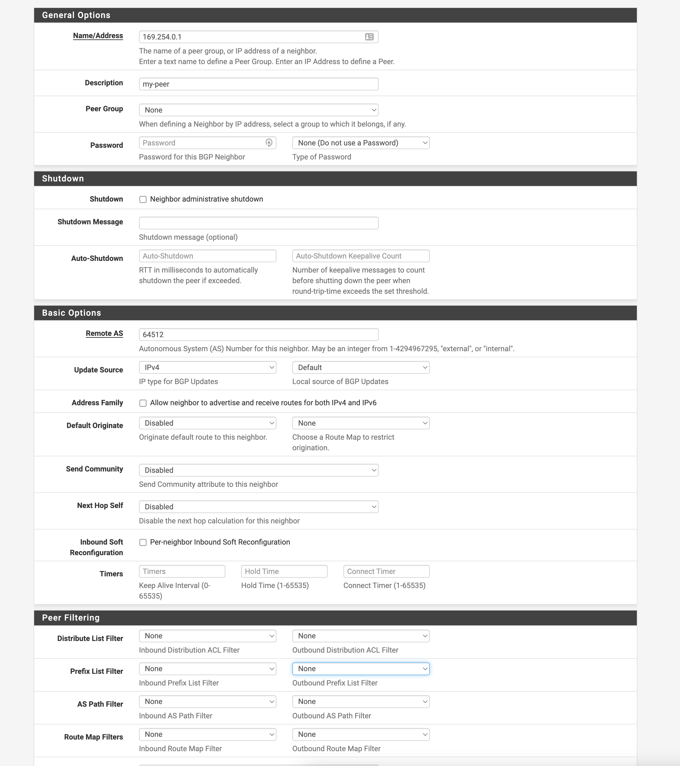
- Go to the Neighbor section of the FRR/BGP page and add a new neighbor with the configuration below, filling in the correct values for Remote AS.
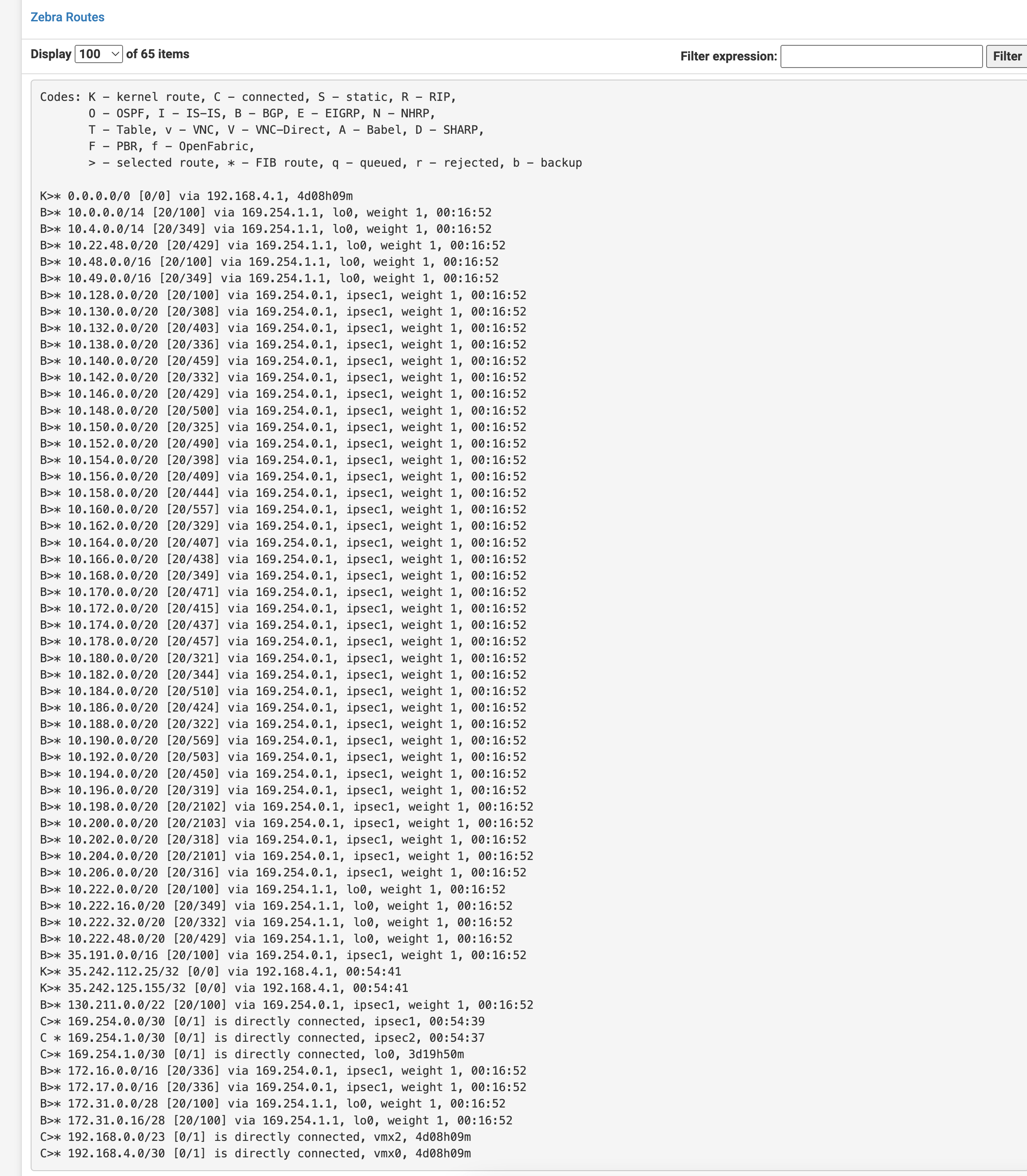
- Next enable your IPsec VPN connection if you haven’t already and go to the BGP status page. You should see your BGP session is successful and routes on both sides are imported/exported
Unifi Configuration
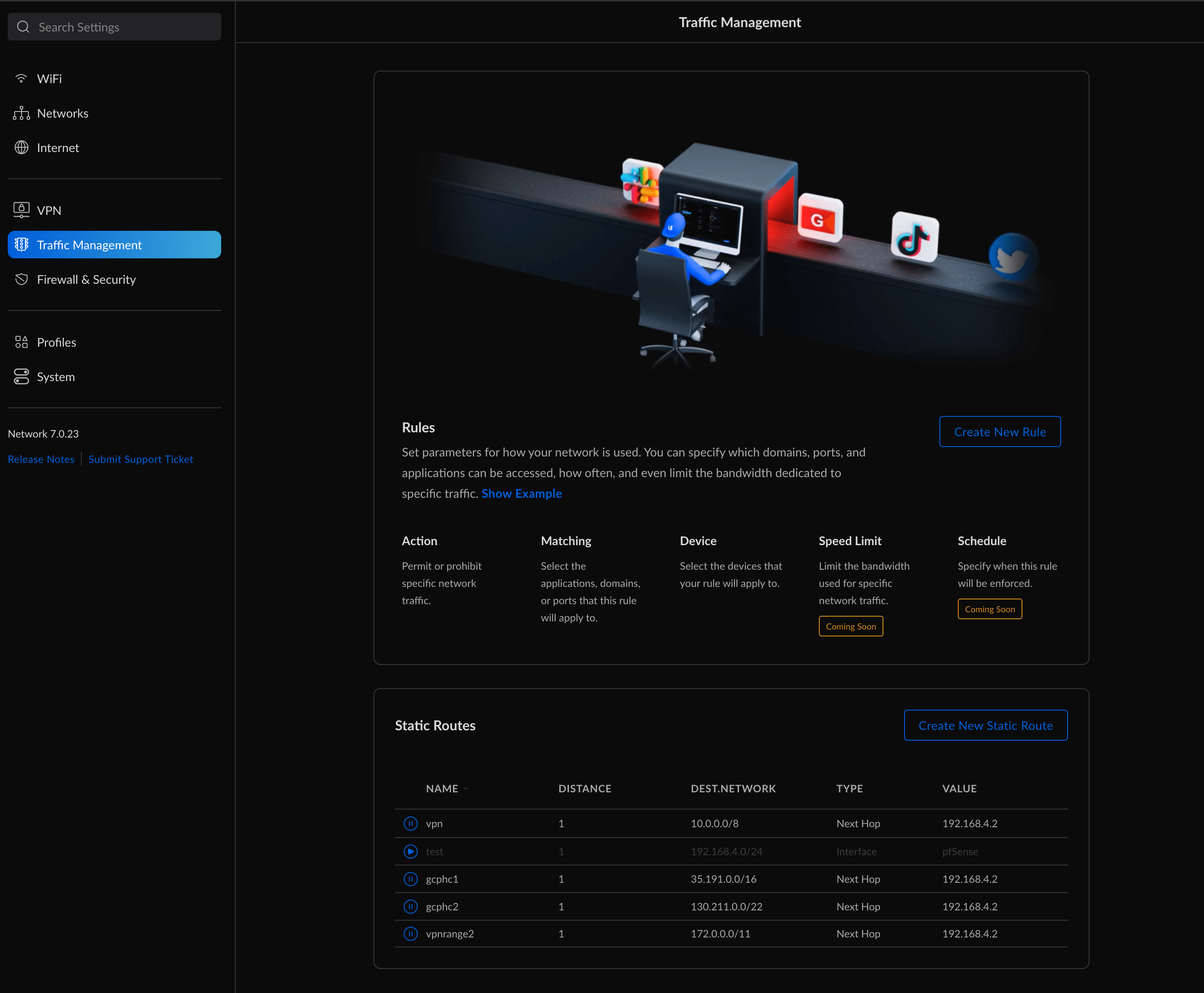
- This next part is only necessary if your pfSense box is behind a router. I have a few static routes configured that tell certain IP ranges their next hop is my pfSense’s private IP so that traffic knows where to go. The gcphc1 and 2 are for health checks if you are setting up a Hybrid NEG and the last one is for control plane master networks on private clusters. I had to do a /11 subnet and not a 12 for some reason because for some reason my /12 subnet didn’t include the last CIDR block of my GCP network.
GCP Configuration for GKE Private Access
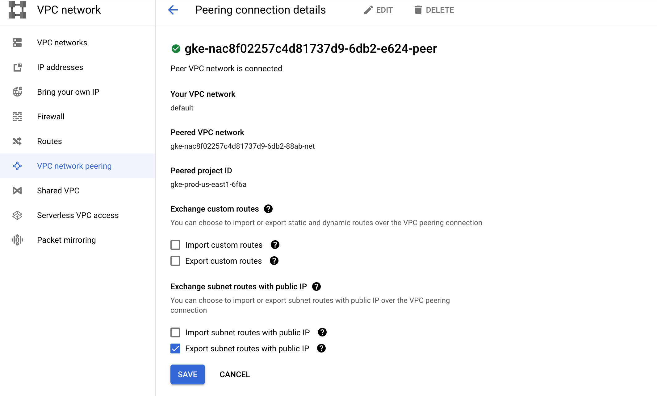
- Go to the peering section of your GCP project and find the network peer that corresponds to your private GKE cluster. You want to edit this peering connection and enable importing and exporting of custom routes, so your BGP router advertises them.
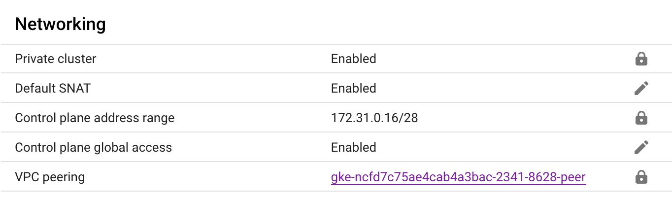
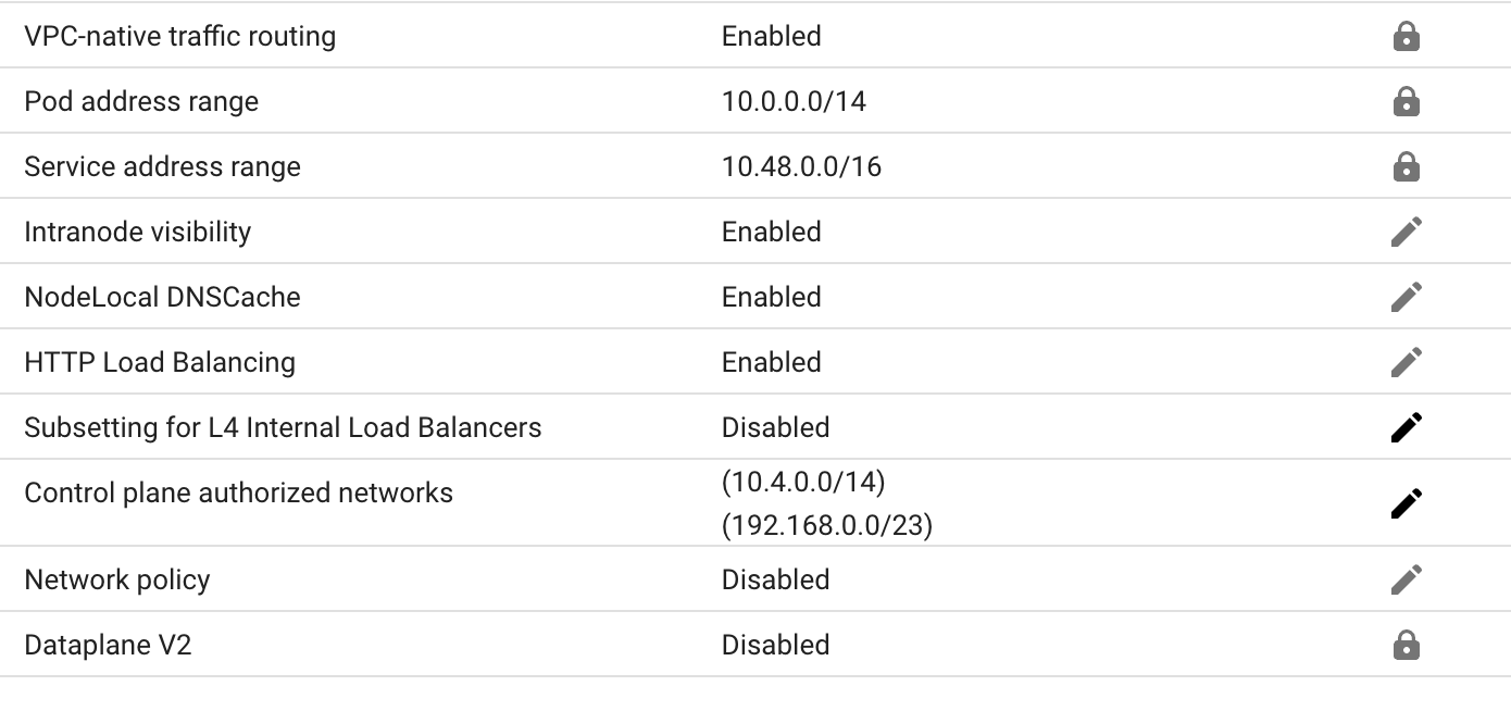
- Go to you GKE cluster and enable control plane global access, this allows subnets on the same network that your cluster isn’t in to access the control plane, this is needed if your VPN gateway region is different then your cluster region or you have multiple clusters. Then add your LAN IP to the control plane authorized networks list.
- Create a firewall rule in your network to allow ingress from your LAN IP address
Conclustion
There you go if you configured everything above then you should be able to run kubectl commands on your private clusters with no external IP address. I also added the Cloud DNS endpoints from my internal GCP recordset to my upstream DNS servers to allow my LAN to resolve any internal domain names.

This Post Has One Comment